The system dashboard plays an important role when real-time system status monitoring and rapid detection of error situations is required. It presents a general view of the running system including metrics, alarms and historical time series data. In addition, a dashboard could present special information such as deployment pipeline status, which is useful especially for the software developers.
Traditional dashboards are usually displayed on computer or TV screen. Therefore, the dashboard must be displayed on the screen to monitor the system status. Is it really necessary? Is there any other way to monitor the system health? An alternative to solve this problem is to build a separate electronic device that is on the table. This device can display the system status f. ex. by lights. The device is an effective way to present system status events immediately without having to see the display.
The AWS Dashboard Console Project
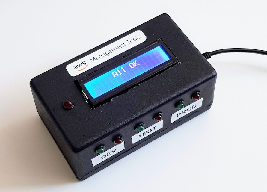
The aim of this project was to create a prototype of the AWS dashboard console using Arduino compatible board and electronic components. The project was mainly a hobby project, but the idea behind was also to create something that I could use in my daily work.
The console presents AWS alerts and codepipeline status by the LED lights and the LCD screen. The console runs independently by polling AWS metrics over WiFi. The console uses NodeMCU microcontroller with an integrated ESP8266 WiFi chip. Just plug in the power and go.
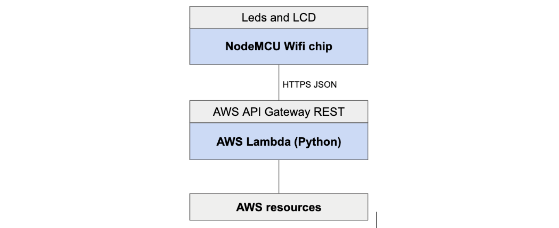
The architecture contains a NodeMCU board and an AWS Lambda backend. The lambda serves AWS status information via a REST interface to the internet. The console polls the REST interface periodically and controls the LED lights and the LCD screen.
Arduino and NodeMCU/ESP8266 microcontroller
Arduino series boards, such as the popular Arduino Uno, contains a simple programmable microprocessor and a set of GPIO connectors for the electronic components. Some of the board models also have an integrated WiFi chip which enables the internet connection. The Arduino compatible boards do not include an operating system which is the main difference compared to the popular Raspberry Pi series boards.
NodeMCU is an Arduino compatible open source IoT board. It includes hardware which is based on the ESP8266/ESP-12 WiFi module. The NodeMCU is comparable to the common Arduino boards; it can be programmed by the Arduino IDE and it stupidly runs the code that is stored to its flash memory.
Circuit of the Console
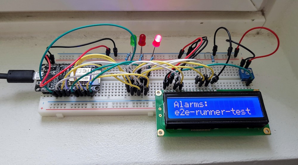
The circuit of the console contains the following components:
- 1 x NodeMCU board
- 1 x LCD 2x16 characters I2C
- 7 x LED lights
- 7 x resistors for the LEDs
- 1 x breadboard
- wires
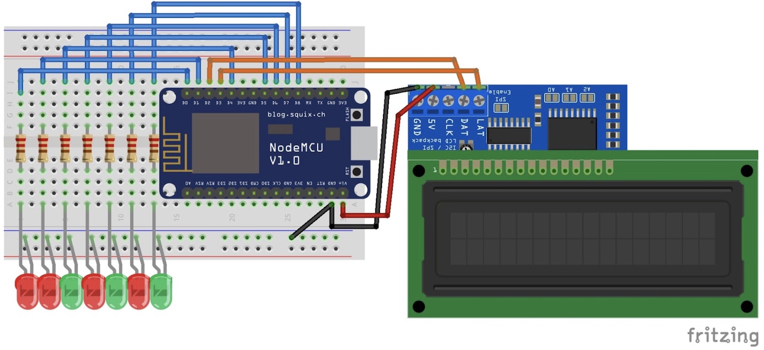
Basic layout of the circuit is relative simple. The LEDs (and resistors) are connected to the NodeMCU IO pins. The LCD screen data wires are connected to the default I2C IO pins. The LCD screen power is connected to the NodeMCU 5V VIN pin. The NodeMCU board is powered by the USB connector. The components are installed in the breadboard to avoid soldering.
Note that this circuit contains a conflict: the NodeMCU board runs by an 3V internal voltage and IO pins are therefore 3V tolerant. On the opposite, the LCD screen requires a 5V voltage. Related to documentation, this circuit should not work since the 5V LCD data wires are connected to the 3V NodeMCU pins. Luckily I found a blog post where this kind of the circuit was proven to work. At least my version of the NodeMCU seems to work fine event the 3V tolerant IO pins are driven by the 5V voltage.
The Arduino program
The Arduino framework programming model contains two main methods: setup and loop. The setup method is run once when the board is powered. The loop method is run infinitely. In addition, you can define own custom methods.
Let’s look at some parts of the code:
#define ALARMS_LED D0
#define PIPE_RUNNING_LED_DEV D8
#define PIPE_FAILED_LED_DEV D7
#define PIPE_RUNNING_LED_TEST D6
#define PIPE_FAILED_LED_TEST D5
#define PIPE_RUNNING_LED_PROD D4
#define PIPE_FAILED_LED_PROD D3

void setup() {
  Serial.begin(115200);

  pinMode(ALARMS_LED, OUTPUT);
  pinMode(PIPE_RUNNING_LED_DEV, OUTPUT);
  pinMode(PIPE_FAILED_LED_DEV, OUTPUT);
  pinMode(PIPE_RUNNING_LED_TEST, OUTPUT);
  pinMode(PIPE_FAILED_LED_TEST, OUTPUT);
  pinMode(PIPE_RUNNING_LED_PROD, OUTPUT);
  pinMode(PIPE_FAILED_LED_PROD, OUTPUT);

  Serial.print("START");

  lcd.init();
  lcd.backlight();

  initConsole();
  connectWifi();

  delay(2000);
  lcd.setCursor(0, 0);
  lcd.print("Call AWS...     ");
  lcd.setCursor(0, 1);
  lcd.print("                ");
}
First, the LED pins are defined. This definition is required to setup which IO pins the LED wires are connected. Then the IO pin mode is set to “OUTPUT” which is required to enable a write mode for the pins.
The LCD screen is initialized and the backlight is switch on. The electronic components are initialized by the custom method initConsole. The initConsole will blink the LEDs and write some text to the screen. Finally, WiFi is connected.
After the setup has finished, start the infinite loop:
void loop() {
  if (WiFi.status() == WL_CONNECTED) {
    // Call the AWS Lambda endpoints
    String data_dev = callAWS(host_dev, "D", api_key_dev);
    String data_test = callAWS(host_test, "T", api_key_test);
    String data_prod = callAWS(host_prod, "P", api_key_prod);

    // Set the console
    setConsole(data_dev, data_test, data_prod);
  } else {
    lcd.print("Wifi Conn lost   ");
  }
}
Each AWS environment (DEV, TEST and PROD) contains it’s own Lambda script to serve status information. Environments are called separately and results are passed to the setConsole method that controls the electronics.
In this context an environment is equal with an AWS account.
The HTTP request is made inside the callAWS method:
 client.print(String("GET ") + url + " HTTP/1.1\r\n" +
               "Host: " + host + "\r\n" +
               "User-Agent: ArduinoRadiatorConsole\r\n" +
               "x-api-key: " + api_key + "\r\n" +
               "Connection: close\r\n\r\n");

  Serial.println("request sent");

  while (client.connected()) {
    String line = client.readStringUntil('\n');

    if (line == "\r") {
      Serial.println("headers received");
      break;
    }
  }

  String line = client.readStringUntil('}');
  line = line + "}";

  client.stop();
The low-level library WiFiClientSecure is used for the HTTP request. High level HTTP libraries are also available but I wanted to stay in basics and decided to use this low level implementation. The HTTP response is read until the closing parenthesis is reach.
After the response is read to the string, it is parsed by a JSON parser. I used the ArduinoJSON library.
The LED lights and the LCD screen content are set inside the setContent method:
digitalWrite(PIPE_RUNNING_LED_DEV, LOW);
digitalWrite(PIPE_FAILED_LED_DEV, LOW);
digitalWrite(PIPE_RUNNING_LED_TEST, LOW);
digitalWrite(PIPE_FAILED_LED_TEST, LOW);
digitalWrite(ALARMS_LED, LOW);
digitalWrite(PIPE_RUNNING_LED_PROD, LOW);
digitalWrite(PIPE_FAILED_LED_PROD, LOW);

if (pipelines_running_dev == true) { digitalWrite(PIPE_RUNNING_LED_DEV, HIGH); }
if (pipelines_failed_dev == true) { digitalWrite(PIPE_FAILED_LED_DEV, HIGH); }
if (pipelines_running_test == true) { digitalWrite(PIPE_RUNNING_LED_TEST, HIGH); }
if (pipelines_failed_test == true) { digitalWrite(PIPE_FAILED_LED_TEST, HIGH); }
if (alarms_raised_prod == true) { digitalWrite(ALARMS_LED, HIGH); }
if (pipelines_running_prod == true) { digitalWrite(PIPE_RUNNING_LED_PROD, HIGH); }
if (pipelines_failed_prod == true) { digitalWrite(PIPE_FAILED_LED_PROD, HIGH); }
First, the LEDs are switch Off to clear the previous state. Then the necessary LEDs are switch On by the simple if clauses.
After the LEDs are fine, write content to the LCD:
  for (int i=0; i < 5; i++) {

    bool all_ok = true;

    if (pipelines_failed_dev == true) {
      lcd.setCursor(0,0);
      lcd.print("DEV Pipe fail:  ");
      lcd.setCursor(0,1);
      lcd.print(pipes_failed_0_dev);

      all_ok = false;
      delay(5000);
    }

    if (alarms_raised_prod == true) {
      lcd.setCursor(0,0);
      lcd.print("PROD Alarms:    ");
      lcd.setCursor(0,1);
      lcd.print(alarms_0_prod);

      all_ok = false;
      delay(5000);
    }

    ...Other clauses...

    if (all_ok == true) {
      lcd.clear();
      lcd.print("     All OK     ");

      delay(60000);

      break;
    }
  }
Every if clause contains 5-second delay to keep the certain text on the screen for a moment. The for loop is used to “blink” all texts few times on the screen. If there is nothing to show, then print “All OK”.
Few examples of the LCD output:
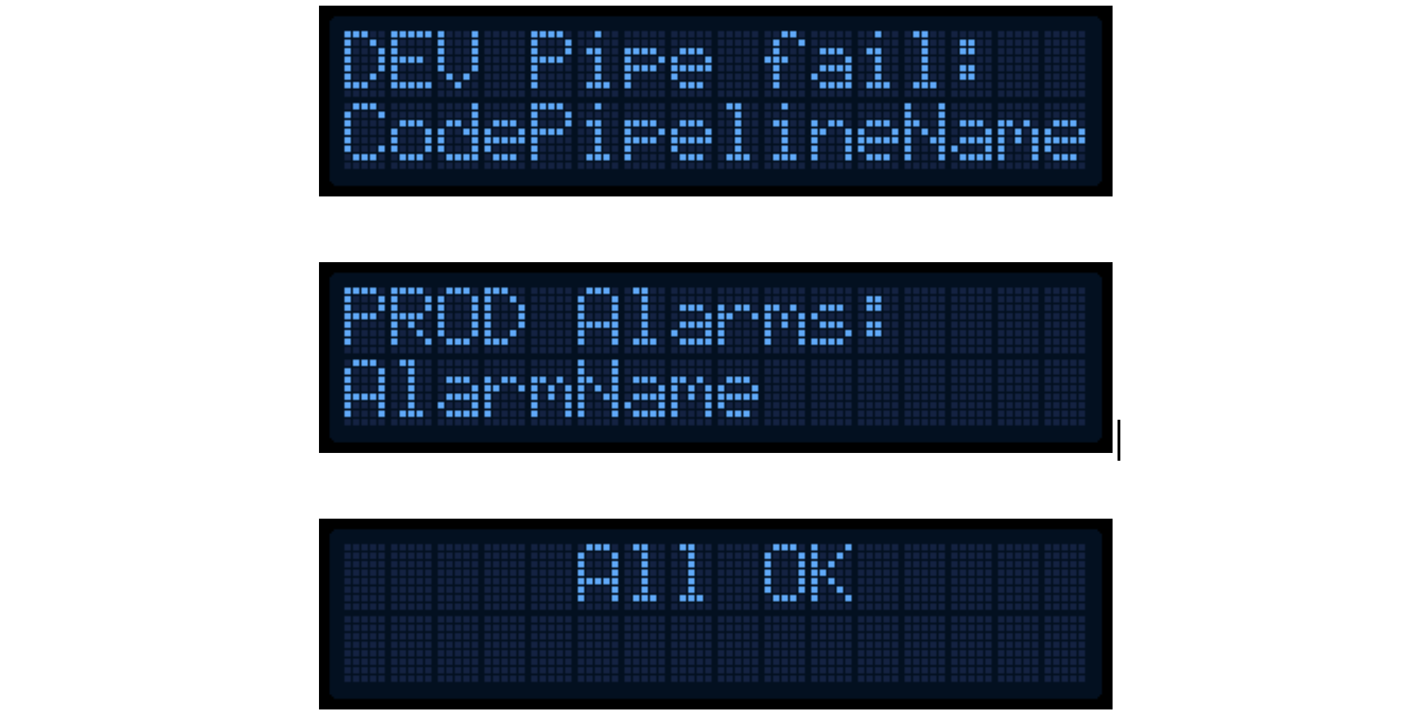
If the string is longer than 16 characters (LCD width), then it is cut.
The LCD library has an extra option to scroll overflowing content on the screen but I note that it was not suitable for this case. Scrolling every string on the screen would take just too much time.
Lambda backend script
AWS status information is served by the simple Lambda script (Python). The Lambda provides a REST interface that includes all the necessary information for the console. The Lambda starts on request and does not contain persistence. The Lambda is published through the AWS API Gateway and secured by an API KEY.
An example of the Lambda response:
{
    "alarms_list": [],
    "alarms_raised": false,
    "alarms_raised_history": false,
    "pipelines_running": false,
    "pipelines_running_list": [],
    "pipelines_failed": false,
    "pipelines_failed_list": []
}
Summary
The project contained a few stages:
- Planning the required components
- Prototyping a first circuit version using a breadboard
- Coding the program
- Building a final version to the box and solder the required wiring
The most laborious stage was building the box and placing all components to it. I found the plastic box from the local electronic shop and made the required holes by a drill and a knife. That took surprising large amount of time and the result is still a bit rough.
Programming was relatively easy, but there was still some troubles along the road. Originally I used an old version of the JSON parser that caused issues. The old version was using C++ pointers that I had never used before. The pointers affected a strange behaviour when the JSON properties were printed to the LCD. After updating the latest version of the JSON parser, everything worked fine.
My original plan was to add fancy mechanical gauges and servo motors to the console. I gave up that idea because I was a bit lazy and couldn’t figure out what kind of benefit the gauges and servos would provide. I still have an idea about the gauges so maybe I will create a second version in the future with a steampunk style :)
An early prototype of the dashboard:
On the following video couple AWS Pipelines were started:
Price of the components
The total price of the components was about 40 euros. The most expensive parts were:
- NodeMCU board 15e
- LCD screen 12e
- Box 5e
- Breadboard 5e